

Fluid Engineering, Inc. is proud to represent Sulzer and its pumping solutions for handling liquids with high air or gas content.
All liquids pumped always contain some gas, usually air, unless this gas has been specifically removed, for instance by boiling. The gases can be present in the liquid in three different states:
- Dissolved in the liquid
- Bound on the particles contained in the liquid.
- As free gas in the form of bubbles.
The amount of gas dissolved in the liquid depends on the gas, liquid, temperature, pressure, etc. This gas dissolved in the liquid does not separate from the liquid unless the liquid pressure is decreased on the liquid temperature is raised. The separation of this dissolved gas is best seen as bubbling just before the liquid begins to boil. This dissolved gas does not usually separate from the liquid, and its content id not considered when the amounts of gas are given.
 The gas bound on the surface of particles contained in the liquid has very small bubbles. Stock fibers that have been dried once contain air their hollow lumen, even after pulping. Under normal conditions, this gas does not disturb pumping, either. However, this air may cause problems in other process equipment such as washers and the wire section of a paper machine.
Air contained in a liquid such as fiber suspension in the form of bubbles disturbs pumping. Bubble-form air is attached to the fibers or it is present between them. The higher the stock consistency, the higher the air content. The air content depends on the stock type, stock characteristics, etc.
Typical values for the air content in stock have been given in Figure 1 at right.
This air in bubble form enters the pumped liquid from several sources such as:
- The cooking process produces carbon dioxide, formic acid, mercaptans, dimethyl sulfide, etc. The oxygen bleaching reaction also produces carbon dioxide.
- In certain processes, air or gas is added into the liquid so as to achieve the desired result. Ink particles are removed from recycled fiber by means of the flotation method, where air is introduced into the stock.
 The process industry commonly uses equipment whose structure allows the mixing of air into the liquid This is particularly problematic in process stages following the cooking process where soap contributes to foaming and mixing of air.
- In the pulp and paper industry, stock drops several meters from almost all filters to a tank situated beneath. Air is efficiently mixed into the stock during this freel fall.
- Stock is often fed into a storage tower through the top of the tower, through its center section.
 The resulting free fall may be over 100 feet or more, causing air to be mixed with the stock.
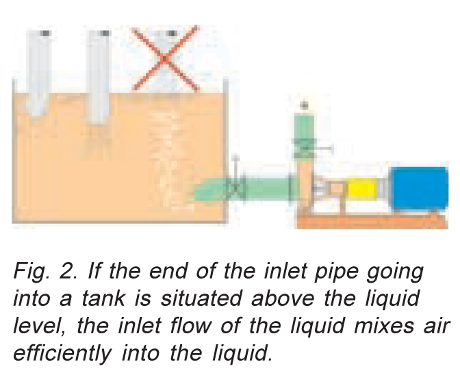
- Inadequatey designed or implemented pumping solutions cause undesirable mixing of gases or air with liquids (Fig. 2, 3 and 4).
- Leaking seals in valves and pumps and other leaks in the vacuum system may also cause air to be mixed into the pumped liquid.
All of the above causes can lead to a situation where pumping with conventional centrifugal pumps is no longer possible.
 The situation is aggravated by factors such as:
- Additives contained in the liquid such as soap, emulsifying agents, detergents, dispersion agents, lignin compounds, and alum.
- Characteristics of the liquid such as stock consistency (the higher the consistency, the higher the air content) and production method used (various types of stocks contain different amounts of air under identical conditions), refining degree (refining increases the air content), fillers, viscosity of the liquid, and temperature of the liquid.
 How does the air problem appear in pumping?
When a conventional centrifugal pump (Fig. 5) pumps a liquid containing a lot of gas or air, such as stock, filtrate water, etc. the free gas or air contained in the liquid begins to gather in front of the impeller. The lighter gas or air is separated at the point of the lowest pressure, which is often in the front of the impeller. Hence, an air or gas bubble is formed here. That section of the vanes of the impeller which is inside the bubble loses some of its pumping efficiency. This way, the output of the pump decreases (Fig. 6). As the bubble grows big enough, it begins to disturb pumping and the operation of the entire process. Pumping may also cease completely. The air or gas bubble remains in front of the impeller for as long as the pump rotates. If the pump is stopped for a while, the bubble will disappear. After restarting, the pump will run normally until a new bubble starts to form. 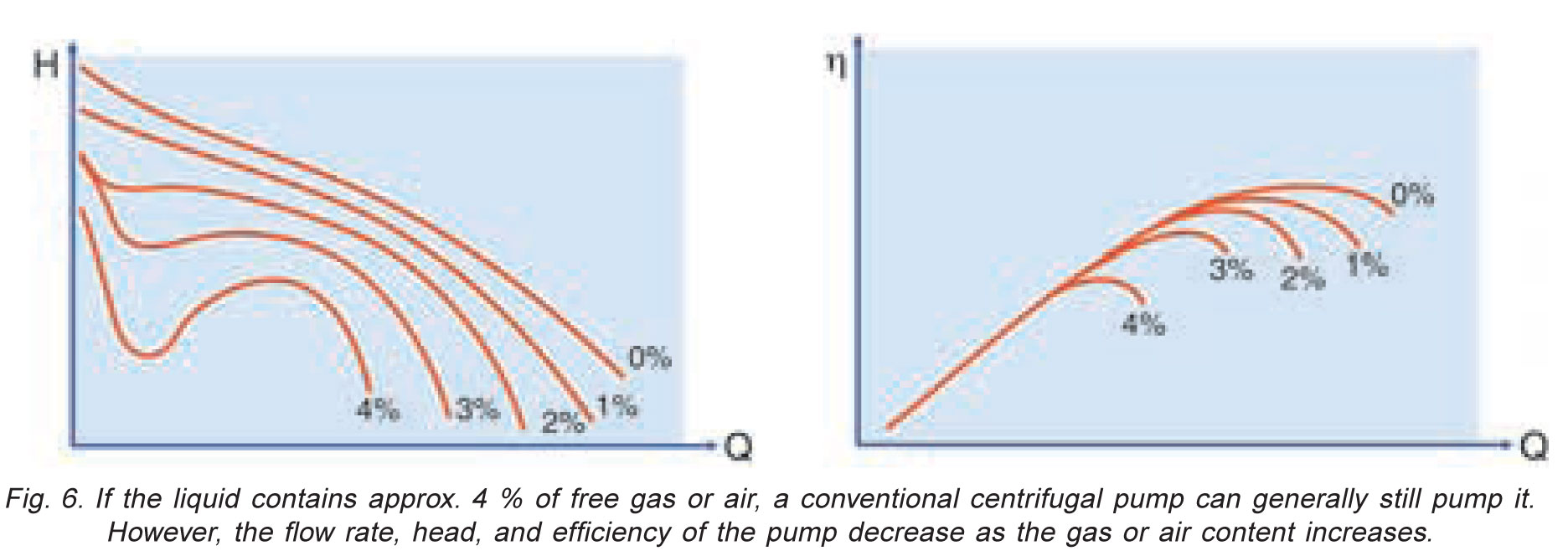 In general, stopping and restarting pumps this way is unacceptable.
What are the traditional means for eliminating disturbances caused by air and gas?
Since stable pumping is imperative in view of the operation of the entire process, factors enabling trouble-free pumping have been studied in the past. The means discovered include, among others, the following:
- Optimizing the conditions on the suction side of the pump:
- Size of suction pipe.
- Shape of suction pipe.
- Correct location of suction pipe in the tank.
- Overdimensioning instructions for pumps have been provided on account of the gas content. These are partly practicable even today.
- Sulzer has studies the various types of impellers, clearances and other design features of pumps that best tolerate liquids containing gas or air. Sulzer has given great attention to the effect of turbulence, for instance in the impeller.
- Use of defoamers. If none of the above means have solved the pumping problem, a common method was and is to use defoamers. However, their cost is often significant and they do have an environmental impact. Some defoamers may cause sedimentation in the process equipment.
- Use of other pump types. If a centrifugal pump has not operated properly using the above means, it has sometimes been replaced with, for instance, a positive displacement pump. However, this solution is not always economical. If the liquid pumped contains solids, which is often the case, screw pumps, lobe rotor pumps, etc. wear rapidly. As the capacities of mills increase, size limitations of positive displacement pumps limit process capacity
New pumps solutions
Sulzer Pumps has developed pump types that, through their operating principal remove disturbing gas or air contained in the liquid so as to maintain proper pumping and to prevent any pumping disturbances resulting from the gas or air. In these pumps, gas or air is removed by creating a certain pressure difference between the suction side of the pump and the degassing chamber, situated behind the impeller. This pressure difference is achieved, for instance, through sufficient inlet head prevailing in front of the pump. If sufficient inlet head cannot be achieved, the pressure difference can be created either with a separate or built-in vacuum pump. By removing the disturbing gas or air in the pump, the pump operation becomes unstable. This also enhances the operation of the entire process and other process equipment.
Sulzer Pumps' pump solutions for liquid containing gas or air
ART Pumps
 The AHLSTARTM APT pump range includes the ART Pumps (Figure 7) which are used to pump stocks containing considerable amounts of gas and air at a consistency range of up to 8%, plus other process liquids. A separate vacuum pump is used in conjunction with the ART Pump if the inlet head on the suction side is low. The ART Pump is also self-priming when a vacuum pump is used with it.
Based on long-term experiences, the ART Pump operates trouble-free with liquids which contain up to 70% of air or gas. The degassing system removes that proportion of the gases or air contained in the liquid which disturbs pumping.
 Operating principle (Figure 8):
In the AHLSTARTM ART Pump air or gas, which is present in the form of a bubble in front of the impeller or some other location with a low pressure, is led to the back of the impeller through the channels in the impeller. There is an expeller on the shaft of the pump, separating liquid from the air or gas which enters through the channels. The liquid is returned along a separate pipe to the inlet side of the pump, and the gas or air is led in another pipe out of the pump.
If the ART pump has a suitable inlet head, no vacuum pump is needed. The removed gas or air can be led directly to a floor channel, for instance.
If no sufficient pressure difference is achieved, the necessary pressure difference is created by means of a separate, small water ring vacuum pump.
If there is a vacuum in the tank, the degassing system is connected to the top part of the tank. No separate vacuum pump is needed in this case.
Depending on the size and speed of the ART Pump, the inlet head in the liquid tank can be 33 to 49 feet of water column. In applications requiring the self priming feature, where a vacuum pump is used, the suction head of the pump can be up to 23 to 26 feet.
In special applications, the ART Pump can remove even more air from the liquid by reducing the pressure on the suction side of the pump. In this case, the volume of the gas increases, which means more efficient gas removal from the liquid.
The ARP Pump is suitable for the following capacities: Flows up to 28,500 GPM and heads up to 590 feet TDH.
 AHLSTARTM AST Pump
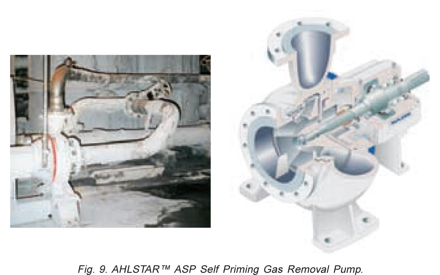
The AHLSTARTM pump range includes also the AST self-priming gas removal pumps (Figure 9). They are highly suitable for the pumping of liquids containing air or gas when the liquids do not contain abrasive particles and when there is a low inlet head or a vacuum on the inlet side of the pump.
Operating Principle (Figure 10):
The AHLSTARTM AST Pump has a small water ring vacuum pump situated behind the impeller. Gas or air enters the vacuum pump through the channels in the impeller.  In order to make gas or air removal possible, a certain pressure difference is maintained between the suction side of the pump and the vacuum pump by means of a vacuum relief valve. The removed gas or air is returned to the suction tank, to collection, or to a floor channel. The vacuum pump obtains the liquid it requires during startup (e.g. from the pumped liquid). Since the AST Pump is provided with a mechanical seal, it requires sealing water during operation. This water is also used as running water in the vacuum pump, for instance during starting. The recommended inlet head in the liquid tank is generally 0 to 11.5 feet. In applications requiring self-priming, the suction head of the AST Pump can be up to 26 feet, depending on the pump size and speed.
When the AST Pump operates as a self priming pump, the discharge valve must be closed upon starting. Once the pump casing is filled with liquid, the pump begins to operate in the same manner as an ordinary centrifugal pump. However, the difference to other self priming centrifugal pumps is that any gas or air disturbing pumping is continuously removed through the vacuum pump.
The ASP Pump is suitable fo the following maximum capacities: Flows up to 20,500 GPM and heads up to 525 feet (at a maximum temperature of 302 Degrees F).
MC® Pumping Systems
 Other pumps suitable for liquids containing gas or air include the Sulzer MC® Pumping Systems (Figure 11). These are used at consistency ranges of up to 18%. The air content in medium consistency stocks can be 10 to 40%, depending on the pumping stage, stock type, temperature, etc. In these pumps, air removal is a basic necessity to enable pumping over the entire medium consistency range.
Practical examples and experiences
In the following practical solutions, we will concentrate on user experiences gained from the above AHLSTARTM ART and AST Pumps.
Processes in recycled fiber mills
Case 1 (Figure 12): The following example is an indication of the effect of air and gas removal on the operation of the pump:
 In a recycled fiber line, unsorted recycled fiber stock is pulped at a consistency of approximately 15%, diluted to approximately 6%, pumped into an intermediate tank, and further to a feeding tank. The consistency in the feeding tank is 3.5%. Strong turbulence, air and foam occur in the feeding tank, and it also contains impurities (plastics, paper clips, sand), which are separated in a high-density cleaner and Spectro screen.
The APT Pump that was originally installed in this application did not operate in a stable manner. This is described by Phase A in Figure 13. The flow rate of the pump began to decrease gradually, with simultaneous operational disturbances in the process.  After a while, operators stopped the pump for a moment and then restarted the pump. This made the run properly for some time, but with a decreased flow rate. The operators continued to stop and restart the pump.
The APT Pump was replaced with a gas and air removal AHLSTARTM ART Pump provided with a separate vacuum pump. The pump operation became stable as shown by Phase B in Figure 13.
Case 2 (Figure 14): Application in a flotation line
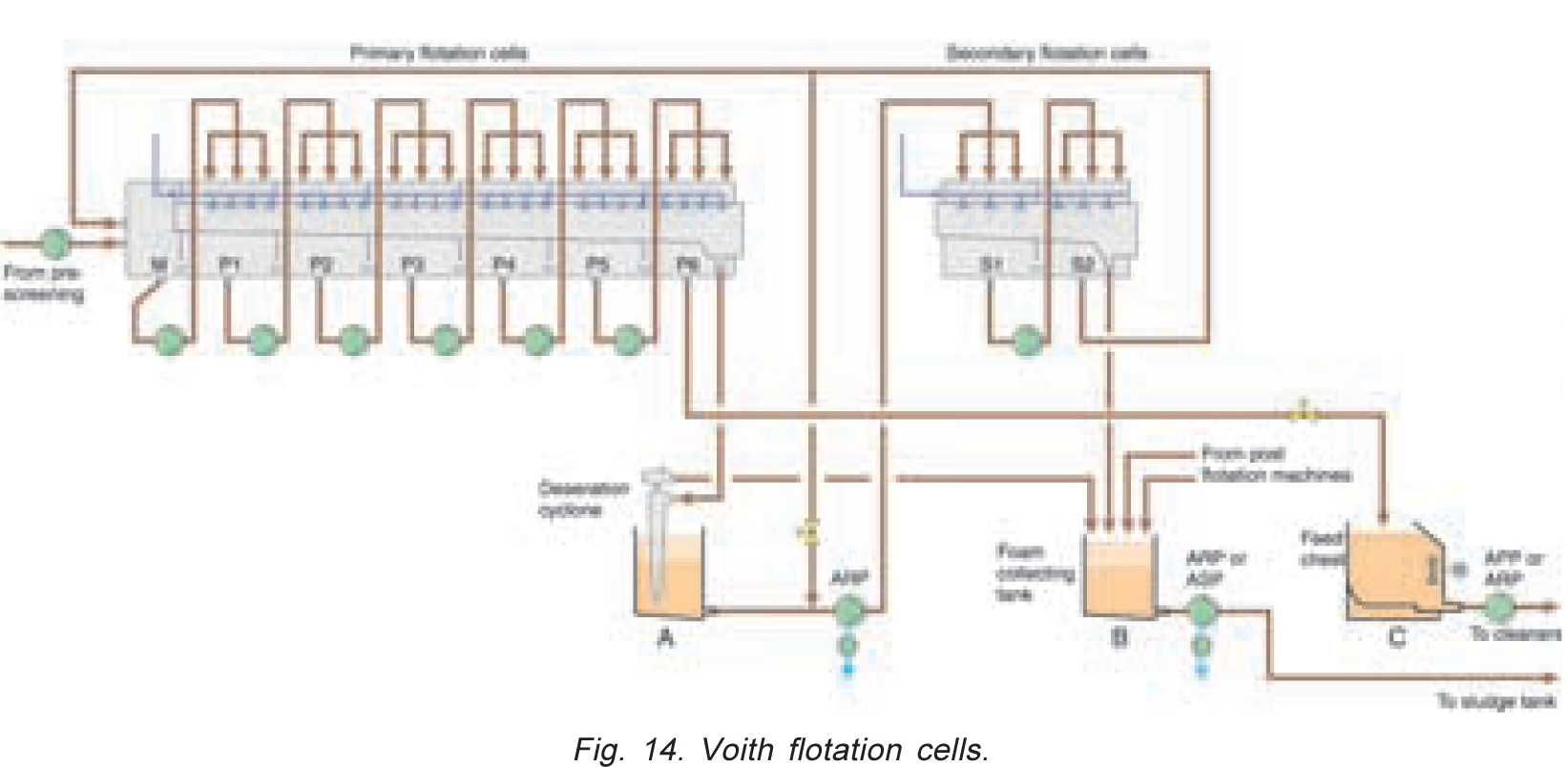
There are several applications in flotation lines (Figure 14), where the liquid pumped contains considerable amounts of air or foam.
A) These types of applications include, for instance, the cyclone tank for stock entering deaeration cyclone through the overflow of primary flotation cells (Figure 14, A), where the pump pumps the air-containing stock with a consistency of approximately 1% to the secondary float cells. The cyclone tank is normally small and contains a lot of foam. Reliable operation here is achieved with the ART or AST Pump.
B) The pump serving the foam collecting tank (Figure 14, B) following the secondary flotation cells is another excellent application for the gas removal pump.
This tank is normally the level is low, and the tank contains a lot of air and foam. In one application, this position was originally provided with an APT Pump where the head was overdimensioned. Attempts were made to keep the pump running by using spray nozzles above the tank to eliminate foaming. Even this did not help.
The APT Pump was replaced with an AHLSTARTM ART Pump. The pump began to operate well with a separate vacuum pump. A similar AHLSTARTM AST Pump can also be used in this position.
C) In some cases, it is also worthwhile installing an ART Pump with degassing for pumping primary flotation cell accept from the feed chest (Figure 14, C) to the cleaners. Depending on the size of the chest, the stock may contain considerable amounts of air which in turn may cause pressure fluctuations. These may give cause to control problems in the system and even impair the separation capacity of the cleaners.
 Case 3 (Figure 15): Pumping recycled fiber to screw presses
A) The following conditions prevailed in a recycled fiber mill application where stock enters the dilution tank from a disc filter.
The consistency of the stock coming from the disc filter is 14 to 17%. The stock is diluted in the feed screw and in the tank to 5.5 to 6%, which was the desired feed consistency for the presses. Both presses had their own feed pumps. Strong turbulence, air, and foam occurred in the tank.
The APT Pumps which were used here were able to pump at a consistency of slightly above 4%. First, only one of the feed pumps was replaced with an AHLSTARTM ART Pump with a separate vacuum pump. The consistency objective was achieved, and the other feed pump was also replaced with an ART Pump.
In recycled fiber applications, the air content can be high, which easily causes problems in stock pumps.
 Is an ART Pump always required?
B) Stock is pumped in an application (Figure 16) resembling the above, with the stock coming from a washer at a consistency of approximately 10 to 12%. The stock is diluted to the desired consistency in a feeding tank situated beneath the washer; in this case, the target consistency was 7 to 7.5%. An ordinary AHLSTARTM APT Stock Pump managed this application without problems. The stock flow was distributed to two different presses. Air content in this particular stock application was low enough to enable proper operation with a conventional stock pump.
 Case 5 (Figure 17): Pumping sludge-containing waste water from the paper mill to waste water treatment.
From a paper mill, sludge-containing waste water is pumped to an outdoor tank with a depth of approximately 16 feet. The consistency of this waste water is 0 to 4%.
A rotary-type displacement displacement pump was earlier used in this application. However, its rubber rotor wore rapidly, since the liquid pumped is also somewhat abrasive. The maintenance costs of the diplacement pump hence were high.
An AHLSTARTM AST Pump with a built-in vacuum pump was installed for trial purposes in the fall of 1996, and the pump worked trouble-free right from the beginning.
The benefits of the AST Pump include:
-Easy use of a centrifugal pump,
-low maintenance costs.
Pulp mill processes
 Case 1 (Figure 18): Pumping soap from the washing department to the evaporation plant.
The cooking process produces a lot of various gases. in conjunction with stock washing, these gases enter the filtrate tank with the wash liquor. Since soap contained in the black liquor makes up very stable foam together with the gases, soap separates on top of the black liquor, from where it is led into a separate soap tank. From the soap tank, soap is pumped to a soap collecting tank situated at the evaporation plant. The density of soap coming from the washing department can be as low as 19 lbs/ft3 because of the gases contained in it.
This difficult mixture has earlier been pumped from the soap tank to the evaporation plant using a lobe rotor pump.
The following problems have been encountered in the use of the lobe rotor pump:
- The soap mixture pumped has foamed from the tank onto the floor, causing additional need for cleaning.
- The lobe rotor pump is an expensive and complicated special pump.
- The pump maintenance is difficult and also its spare parts are expensive.
The AHLSTARTM ART Pump with a degassing system was installed for the first time at a pulp mill in 1991 to pump the soap mixture from the washing department to the evaporation plant, where the actual soap separation from black liquor takes place. The inlet head in the soap tank varies between 0 and 3 feet.
The ART Pump has been working well here. After this, several other ART Pumps and more recently also AST Pumps with a built-in vacuum pump have been installed in various applications both at the cooking plant and at the washing department.
Benefits brought by the AHLSTARTM ART and AST Pumps:
- The disadvantages of lobe rotor pumps are eliminated.
- Improved soap separation.
- Better, fiber-free soap quality (pumping through fiber filter).
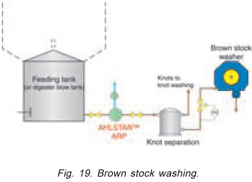 Case 2 (Figure 19): Feeding brown stock to washer.
At a pulp mill, brown stock is pumped from a blow tank into an intermediate tank. From the intermediate tank, an APT Pump pumped this stock with a consistency of 3 to 5% via knot separation to a washer. The brown stock temperature was approximately 195°F, and it contained a lot of gas, air and foam. The problem was that the entrained air caused fluctuations in the display of the feed flow rate measurement. This in turn resulted in control problems.
In June 1997, a gas and air removal AHLSTARTM ART Pump with a separate degassing system was installed in this service. After the installation, there have been no problems in flow rate measurement.
In this application, the ART Pumps gives the following advantages:
- Better runnability at the washing department, as the feed flow rate is under control.
- Improved drainage at the washer.
- More opportunities to optimize brown stock washing.
TMP plant processes
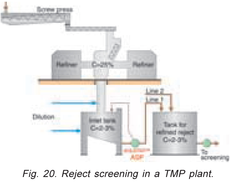 Case 1 (Figure 20): Pumping TMP reject from refiners to refined reject tank.
The reject handling system at the TMP department of a paper mill was modernized. In this conjunction, the mill wanted to replace the existing transfer system where five screws transferred the 25% refined reject to a reject tank. In the reject tank, the stock was diluted to 2 to 3%. From the reject tank, the stock was pumped further to screening.
In the new solution, an inlet tank was installed under the refiners on the floor below, where the stock was diluted directly to 2 to 3%. It was also assumed that the stock contains a lot of air and that the tank has a low level. The pump selection process concluded in the gas and air removing AHLSTARTM AST Pump with a built-in degassing system. The degassing return pipe was led back into the inlet tank.
The gas and air removing AST Pump has operated well in this application since spring 1997. The AST Pump features the following benefits:
- Simple transfer system,
- low maintenance costs,
- additional reliability at the mill.
Paper mill processes
 Case 1 (Figure 21): Deflaking and pumping of broke stock to machine chest.
At the stock preparation department of a paper mill, broke stock is pulped at a consistency of 5 to 7%. After pulping, the stock is pumped into two alternate tanks using an AHLSTARTM NPT Pump. In order to guarantee good stock quality, stock is recirculated 2 to 3 times through a deflaker using a conventional stock pump situated between the tanks. After this, the stock is pumped from the tank into mixing chest. The inlet head in the tank varies between 15 and 0 feet. At the end of the emptying stage, at a small inlet head, the air contained in the stock began to separate in front of the impeller, and the pump was not able to empty the tank completely. The mill carries out several color changes due to a certain production program. It is very important to empty the tank completely to miminize the proportion of waste stock.
An AHLSTARTM ART air removal pump without a vacuum pump was installed as the recirculation and emptying pump. The ART Pump features an air separating expeller behin the impeller, separating from the stock any air which disturbs pumping. The stock is returned to the suction side of the pump, and the degassing pipe is led to the top of the tank. With this configuration, the AHLSTARTM ART Pump empties the tank completely, eliminating the amount of waste stock.
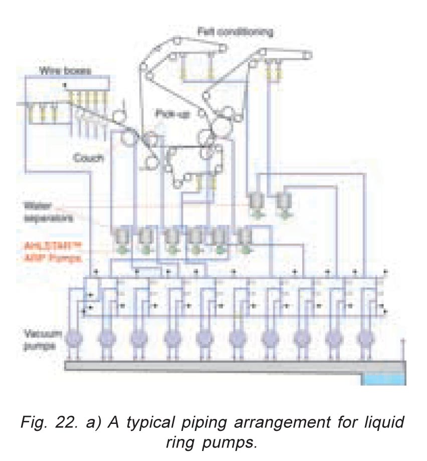 Case 2 (Figure 22): Separating and pumping white water from water separators in the vacuum system of a paper machine or pulp drying machine; replacing the barometric leg.
Water removed from the web of a paper machine by means of vacuum is separated in water separators situated between the paper machine and the vacuum system. It is important that this water is separated as completely as possible so that only moist air goes into the vacuum pump.
Until the development of the Sulzer AHLSTARTM Degassing Pumps, the most reliable means to lead away the separated water from the water separators has been to use barometric legs, i.e. pipes led into a sealed pit. The necessary vacuum of up to 21 in Hg requires a seal pit depth of approximately 33 feet, which is relatively expensive to make. Moreover, the length of the vertical pumps required in seal pit service, approximately 33 feet, means that the pumps are difficult to service. The pumps also need a level control system because of the risk of running the pumps dry.
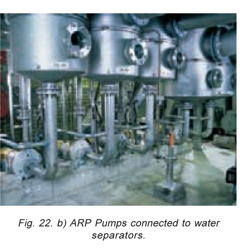 Experience has shown that by installing an air and gas separating AHLSTARTM ART Pump immediately below the water separator, water separation is at least as reliable as with the use of the barometric legs.
Advantages given by the use of ARP Pump:
- Simple location of water separators.
- Water separated at the various suction locations can be easily led to the desired applications.
- No need for level control equipment in the water separators.
- No need for deep seal pits, long barometric legs, or vertical pumps.
Summary
 Features and benefits of air and gas removal AHLSTARTM ART and AST Pumps in pulp and paper applications:
- Difficult and even to date unsolved pumping problems have been solved.
- Trouble free process operation despite high air content.
- The efficiency of other process equipment is improved due to gas and air removal.
- The need for expensive antifoam agent is reduced.
- The need for chemicals which negatively affect the environment is consequently reduced.
- Overall pumping efficiency is improved.
- Most of the spare parts are interchangeable with the other AHLSTARTM Pumps.
- An APT Pump can be later converted into an ART Pump and vice versa.
Jasa Sedot Limbah Bandung Putra
Managing Stock, Liquors and Other Liquids With High Air or Gas Content
wedding djs bozeman montana
Get here expert master djs bozeman montana currently taking on new clients and reasonably priced now!